- 您现在的位置:买卖IC网 > Sheet目录307 > ADE7758ARWZRL (Analog Devices Inc)IC ENERGY METERING 3PHASE 24SOIC
�� �
�
�Data� Sheet�
�ZERO-CROSSING� DETECTION�
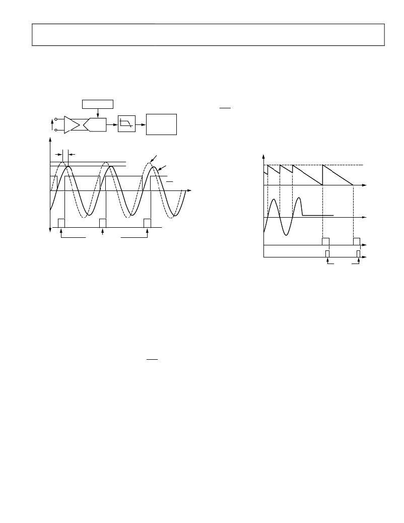
�The� ADE7758� has� zero-crossing� detection� circuits� for� each� of�
�the� voltage� channels� (VAN,� VBN,� and� VCN).� Figure� 51� shows�
�how� the� zero-cross� signal� is� generated� from� the� output� of� the�
�ADC� of� the� voltage� channel.�
�ADE7758�
�every� time� a� zero� crossing� is� detected� on� its� associated� input.�
�The� default� value� of� ZXTOUT� is� 0xFFFF.� If� the� internal� register�
�decrements� to� 0� before� a� zero� crossing� at� the� corresponding�
�input� is� detected,� it� indicates� an� absence� of� a� zero� crossing� in�
�the� time� determined� by� the� ZXTOUT[15:0].� The� ZXTOx�
�detection� bit� of� the� corresponding� phase� in� the� interrupt� status�
�GAIN[6:5]�
�×1,� ×2,� ×4�
�REFERENCE�
�register� is� then� switched� on� (Bit� 6� to� Bit� 8).� An� active� low� on� the�
�IRQ� output� also� appears� if� the� ZXTOx� mask� bit� for� the�
�VAN,�
�VBN,�
�VCN�
�PGA�
�ADC�
�ZERO-�
�CROSSING�
�DETECTOR�
�corresponding� phase� in� the� interrupt� mask� register� is� set� to�
�Logic� 1.� Figure� 52� shows� the� mechanism� of� the� zero-crossing�
�1.0�
�0.908�
�24.8°� @� 60Hz�
�LPF1�
�f� –3dB� =� 260Hz�
�ANALOG� VOLTAGE�
�WAVEFORM�
�(VAN,� VBN,� OR� VCN)�
�LPF1�
�OUTPUT�
�timeout� detection� when� the� Line� Voltage� A� stays� at� a� fixed� dc�
�level� for� more� than� 384/CLKIN� � ZXTOUT[15:0]� seconds.�
�16-BIT� INTERNAL�
�REGISTER� VALUE�
�ZXTOUT[15:0]�
�IRQ�
�VOLTAGE�
�CHANNEL� A�
�READ� RSTATUS�
�Figure� 51.� Zero-Crossing� Detection� on� Voltage� Channels�
�The� zero-crossing� interrupt� is� generated� from� the� output� of�
�LPF1.� LPF1� has� a� single� pole� at� 260� Hz� (CLKIN� =� 10� MHz).� As�
�a� result,� there� is� a� phase� lag� between� the� analog� input� signal� of�
�the� voltage� channel� and� the� output� of� LPF1.� The� phase� response�
�of� this� filter� is� shown� in� the� Voltage� Channel� Sampling� section.�
�The� phase� lag� response� of� LPF1� results� in� a� time� delay� of�
�approximately� 1.1� ms� (at� 60� Hz)� between� the� zero� crossing� on�
�the� voltage� inputs� and� the� resulting� zero-crossing� signal.� Note�
�that� the� zero-crossing� signal� is� used� for� the� line� cycle�
�accumulation� mode,� zero-crossing� interrupt,� and� line�
�period/frequency� measurement.�
�When� one� phase� crosses� from� negative� to� positive,� the�
�corresponding� flag� in� the� interrupt� status� register� (Bit� 9� to�
�Bit� 11)� is� set� to� Logic� 1.� An� active� low� in� the� IRQ� output� also�
�appears� if� the� corresponding� ZX� bit� in� the� interrupt� mask�
�register� is� set� to� Logic� 1.� Note� that� only� zero� crossing� from�
�negative� to� positive� generates� an� interrupt.�
�The� flag� in� the� interrupt� status� register� is� reset� to� 0� when� the�
�interrupt� status� register� with� reset� (RSTATUS)� is� read.� Each�
�phase� has� its� own� interrupt� flag� and� mask� bit� in� the� interrupt�
�register.�
�Zero-Crossing� Timeout�
�Each� zero-crossing� detection� has� an� associated� internal� timeout�
�register� (not� accessible� to� the� user).� This� unsigned,� 16-bit�
�register� is� decreased� by� 1� every� 384/CLKIN� seconds.� The�
�registers� are� reset� to� a� common� user-programmed� value,� that� is,�
�the� zero-crossing� timeout� register� (ZXTOUT[15:0],� Address� 0x1B),�
�ZXTOA�
�DETECTION� BIT�
�READ�
�RSTATUS�
�Figure� 52.� Zero-Crossing� Timeout� Detection�
�PHASE� COMPENSATION�
�When� the� HPF� in� the� current� channel� is� disabled,� the� phase�
�error� between� the� current� channel� (IA,� IB,� or� IC)� and� the�
�corresponding� voltage� channel� (VA,� VB,� or� VC)� is� negligible.�
�When� the� HPF� is� enabled,� the� current� channels� have� phase�
�response� (see� Figure� 53� through� Figure� 55).� The� phase� response�
�is� almost� 0� from� 45� Hz� to� 1� kHz.� The� frequency� band� is� sufficient�
�for� the� requirements� of� typical� energy� measurement� applications.�
�However,� despite� being� internally� phase� compensated,� the�
�ADE7758� must� work� with� transducers� that� may� have� inherent�
�phase� errors.� For� example,� a� current� transformer� (CT)� with� a�
�phase� error� of� 0.1°� to� 0.3°� is� not� uncommon.� These� phase� errors�
�can� vary� from� part� to� part,� and� they� must� be� corrected� to�
�perform� accurate� power� calculations.�
�The� errors� associated� with� phase� mismatch� are� particularly�
�noticeable� at� low� power� factors.� The� ADE7758� provides� a�
�means� of� digitally� calibrating� these� small� phase� errors.� The�
�ADE7758� allows� a� small� time� delay� or� time� advance� to� be�
�introduced� into� the� signal� processing� chain� to� compensate� for�
�the� small� phase� errors.�
�The� phase� calibration� registers� (APHCAL,� BPHCAL,� and�
�CPHCAL)� are� twos� complement,� 7-bit� sign-extended� registers�
�that� can� vary� the� time� advance� in� the� voltage� channel� signal�
�path� from� +153.6� μs� to� ?75.6� μs� (CLKIN� =� 10� MHz),�
�Rev.� E� |� Page� 23� of� 72�
�发布紧急采购,3分钟左右您将得到回复。
相关PDF资料
ADE7761AARSZ-RL
IC ENERGY METERING 1PHASE 20SSOP
ADE7761BARSZ-RL
IC ENERGY METERING 1PHASE 20SSOP
ADE7768ARZ-RL
IC ENERGY METERING 1PHASE 16SOIC
ADE7769ARZ-RL
IC ENERGY METERING 1PHASE 16SOIC
ADM8843ACPZ-REEL7
IC LED DRVR WHITE BCKLGT 16LFCSP
ADP1653ACPZ-R7
IC LED DRVR PHOTO FLASH 16-LFCSP
ADP1712-EVALZ
BOARD EVALUATION ADP1712
ADP1720-EVALZ
BOARD EVAL FOR ADP1720-ADJ
相关代理商/技术参数
ADE7759
制造商:AD 制造商全称:Analog Devices 功能描述:Active Energy Metering IC with di/dt Sensor Interface
ADE7759ARS
功能描述:IC ENERGY METERING 1PHASE 20SSOP RoHS:否 类别:集成电路 (IC) >> PMIC - 能量测量 系列:- 产品培训模块:Lead (SnPb) Finish for COTS
Obsolescence Mitigation Program 标准包装:2,500 系列:*
ADE7759ARSRL
功能描述:IC ENERGY METERING 1PHASE 20SSOP RoHS:否 类别:集成电路 (IC) >> PMIC - 能量测量 系列:- 产品培训模块:Lead (SnPb) Finish for COTS
Obsolescence Mitigation Program 标准包装:2,500 系列:*
ADE7759ARSZ
功能描述:IC ENERGY METERING 1PHASE 20SSOP RoHS:是 类别:集成电路 (IC) >> PMIC - 能量测量 系列:- 产品培训模块:Lead (SnPb) Finish for COTS
Obsolescence Mitigation Program 标准包装:2,500 系列:*
ADE7759ARSZRL
功能描述:IC ENERGY METERING 1PHASE 20SSOP RoHS:是 类别:集成电路 (IC) >> PMIC - 能量测量 系列:- 产品培训模块:Lead (SnPb) Finish for COTS
Obsolescence Mitigation Program 标准包装:2,500 系列:*
ADE7760
制造商:AD 制造商全称:Analog Devices 功能描述:Energy Metering IC with On-Chip Fault Detection
ADE7760ARS
制造商:Analog Devices 功能描述:Energy Measurement 20-Pin SSOP 制造商:Analog Devices 功能描述:ENERGY METER IC W/ ONCHIP FAULT & OSCIL. - Rail/Tube
ADE7760ARSRL
制造商:Analog Devices 功能描述:Energy Measurement 20-Pin SSOP T/R 制造商:Analog Devices 功能描述:ENERGY METER IC W/ONCHIP FAULT & OSCIL. - Tape and Reel